
ECM/ECU
Cummins CM850 ECM Wiring Diagram
The Cummins CM850 ECM wiring diagram, covering ECM connector pinouts, sensor circuits, and the power generation interface used on QST30 units fitted with the CM850 electronic control module.
Cummins
Wiring Diagram
English
Cummins
Wiring Diagram
English
Manual Overview
The Cummins CM850 ECM Wiring Diagram is a detailed electrical reference for integrating the QST30 power-generation engine with its OEM equipment controls. The single-sheet drawing maps the CM850 ECM to the 60-pin engine harness, 50-pin OEM harness and four-pin power connection while identifying the principal sensor, switch, actuator, grounding and communication circuits. Color-coded conductors distinguish DC supply wiring, input signals, grounds and returns, controlled outputs and data links, helping technicians follow individual circuit paths across the diagram.
Connector-face views support cavity and pin identification during harness inspection, continuity testing or connector repair. The document is especially useful to generator technicians, engine-electronics specialists and commissioning personnel. Because individual equipment applications may not activate every circuit shown, the diagram should be used with the relevant generator-set documentation and equipment-specific wiring information.
Technical Specs
| Parameter | Value |
|---|---|
| Engine Series | QST30 |
| Primary Control Module | CM850 ECM |
| Document Type | Power Generation Interface Wiring Diagram |
| Bulletin Number | 4021683-02 |
| Engine Harness Interface | 60-pin connector |
| OEM Harness Interface | 50-pin connector |
| Power Interface | Four-pin power harness |
| Default Conductor Size | 18 AWG unless otherwise noted |
| Document Length | One sheet |
Wiring Colour and Circuit Guide
| Drawing Colour | Circuit Function |
|---|---|
| Red | DC-voltage and power-supply circuits |
| Blue | Input signals from sensors, switches and equipment controls |
| Black | Grounds, shields and return circuits |
| Purple | ECM output signals and controlled circuits |
| Green | Electronic data-link communication circuits |
Use connector identifiers and pin positions as the primary circuit reference. Wire colours support tracing but should not be treated as the only means of identification. Some circuits shown are application dependent and may be inactive on a particular generator set.
Testing and Application Considerations
This wiring drawing does not contain a fault-code matrix or step-by-step diagnostic procedures. It should be used to trace circuits after the applicable troubleshooting information has identified a suspected input, output, power supply, ground or communication circuit.
Before performing continuity, resistance or voltage measurements, identify the correct connector and terminal. Inspect connectors for loose terminals, corrosion, damaged seals, backed-out pins or wiring abrasion. Power and ground circuits should be verified before an ECM, sensor or actuator is replaced.
Not every circuit shown is active in every QST30 application. Consult the generator-set manufacturer’s electrical documentation to determine which optional signals and controls are installed. Do not apply external voltage to an ECM terminal unless the relevant Cummins testing procedure specifically requires it.
Related Manuals
Cummins CM850 Troubleshooting Manual V3 – ISB/QSB/ISC
Cummins CM850 troubleshooting manual V3covering ISB, QSB, ISC, QSC, ISL and QSL9 engine diagnostics and repair.

Important Safety Notice: Before installing, operating, servicing, or troubleshooting this equipment, verify that this manual matches your exact model and serial number. Always read and follow the manufacturer's safety instructions.
Read Online
Table of Contents
Loading contents…
More From
ECM/ECU

Perkins 1306 Diagnostic Guide
Perkins 1306 diagnostic guide covering self-tests, open-circuit testing, flash codes, ECM faults, and engine troubleshooting.
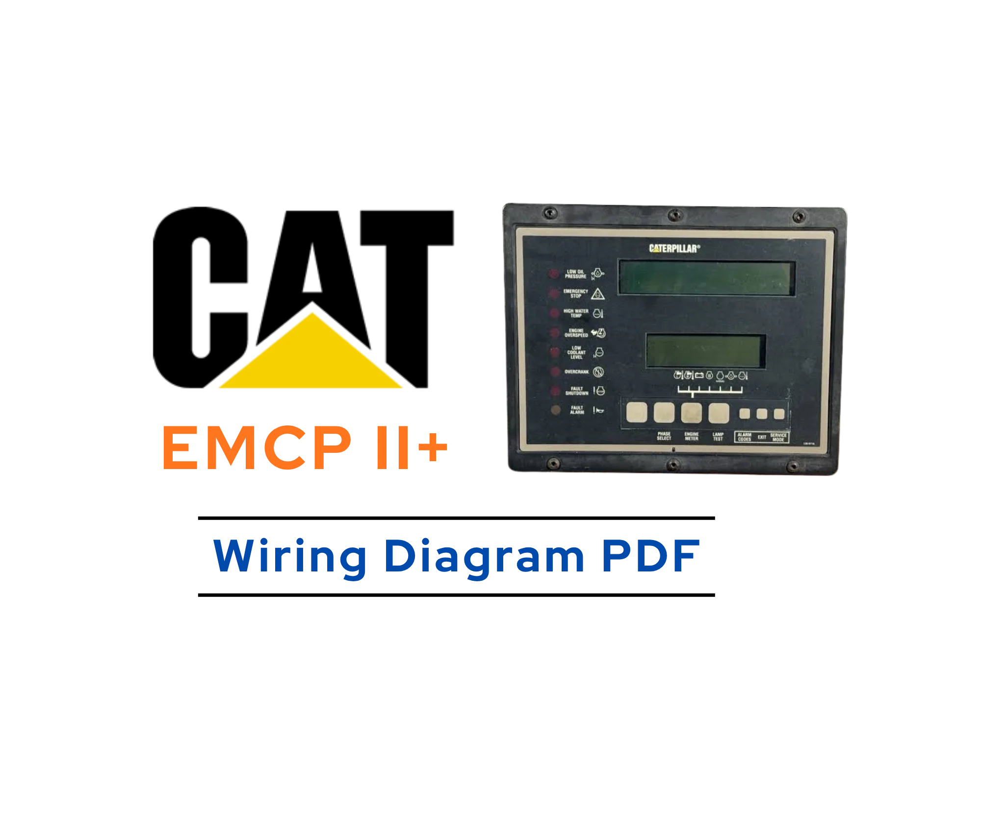
Caterpillar EMCP II+ Schematics and Wiring Diagrams
CAT EMCP II+ electrical schematics covering control circuits, auxiliary systems, protection, load sharing, and generator-set wiring.

CAT 3126B & 3126E Wiring Diagram PDF
Convers ECM connections, sensors, injectors, starting circuits, and vehicle wiring interfaces.
CAT C32 Generator Set ECM Wiring Diagram
This wiring diagram covers the connector pinout layout between the C32 generator set ECM.
Volvo Penta EMS 2 ECU Wiring Diagram (TAD1640-1642GE/VE)
This wiring diagram was released as an update to the wiring schedule for the EMS 2 ECU system.

Volvo D16D Engine ECU Fault Tracing
Volvo D16D Engine ECU/ECM, Fault Tracing Guide Checklist M.
Free, and staying that way
Saved hundreds on a technician call? A quick $3 coffee keeps this independent library running and growing.
☕ Buy the Archivist a CoffeeSpot something off?
Wrong revision, dead link, or spec that doesn't match your unit? Tell us, and we'll check it.
Report an Issue